Merhabalar STm32f407VG kartı ile Registerlar ile PWM kontrolü yapacağız.
1- ” RCC Configuration ” işlemi için tıklayın.
[button text=”Tıkla ve Git” new_tab=”yes” size=”small” icon=”” url=”https://samettasoglu.com/2023/03/14/stm32f407vg-register-ile-system-clock-ayari/”]
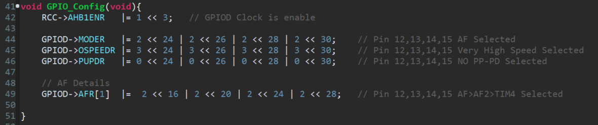
2-” GPIO Configuration” işlemi için bir fonksiyon oluşturuyoruz.
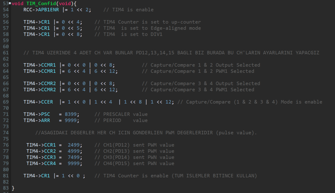
3-” TIMER Configuration” işlemi için bir fonksiyon oluşturuyoruz.
4- Tüm Fonksiyonları “main” içerisinde çağırıyoruz.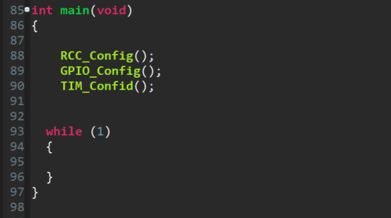
Tüm Kod:
#include “stm32f4xx.h”
#include “stm32f4_discovery.h”
void RCC_Config(void) {
RCC->CR &= ~(1 << 0);
RCC->CR |= (1 << 16);
while (!(RCC->CR & (1 << 17)))
;
RCC->CR |= (1 << 19);
//———————————
RCC->PLLCFGR = 0;
RCC->PLLCFGR |= (1 << 22);
RCC->PLLCFGR |= (1 << 2);
RCC->PLLCFGR |= (168 << 6);
RCC->PLLCFGR |= (0 << 24);
RCC->CR |= (1 << 24);
while ((RCC->CR & (1 << 25)) == 0)
;
RCC->CFGR &= ~(3 << 0);
RCC->CFGR &= ~(0xF << 4);
RCC->CFGR |= (101 << 10);
RCC->CFGR |= (100 << 13);
//———————————
RCC->CIR |= (1 << 19);
RCC->CIR |= (1 << 20);
//———————————
}
void GPIO_Config(void){
RCC->AHB1ENR |= 1 << 3;// GPIOD Clock is enable
GPIOD->MODER |= 2 << 24 | 2 << 26 | 2 << 28 | 2 << 30;// Pin 12,13,14,15 AF Selected
GPIOD->OSPEEDR |= 3 << 24 | 3 << 26 | 3 << 28 | 3 << 30;// Pin 12,13,14,15 Very High Speed Selected
GPIOD->PUPDR |= 0 << 24 | 0 << 26 | 0 << 28 | 0 << 30;// Pin 12,13,14,15 NO PP-PD Selected
// AF Details
GPIOD->AFR[1] |= 2 << 16 | 2 << 20 | 2 << 24 | 2 << 28;// Pin 12,13,14,15 AF>AF2>TIM4 Selected
}
void TIM_Confid(void){
RCC->APB1ENR |= 1 << 2; // TIM4 is enable
TIM4->CR1 |= 0 << 4;// TIM4 Counter is set to up-counter
TIM4->CR1 |= 0 << 5;// TIM4 is set to Edge-aligned mode
TIM4->CR1 |= 0 << 8;// TIM4 is set to DIV1
// TIM4 UZERINDE 4 ADET CH VAR BUNLAR PD12,13,14,15 BAGLI BIZ BURADA BU CH’LARIN AYARLARINI YAPACGIZ
TIM4->CCMR1 |= 0 << 0 | 0 << 8;// Capture/Compare 1 & 2 Output Selected
TIM4->CCMR1 |= 6 << 4 | 6 << 12;// Capture/Compare 1 & 2 PWM1 Selected
TIM4->CCMR2 |= 0 << 0 | 0 << 8;// Capture/Compare 3 & 4 Output Selected
TIM4->CCMR2 |= 6 << 4 | 6 << 12;// Capture/Compare 3 & 4 PWM1 Selected
TIM4->CCER |= 1 << 0 | 1 << 4 | 1 << 8 | 1 << 12;// Capture/Compare (1 & 2 & 3 & 4) Mode is enable
TIM4->PSC = 8399;// PRESCALER value
TIM4->ARR = 9999;// PERIOD value
//ASAGIDAKI DEGERLER HER CH ICIN GONDERLIEN PWM DEGERLERIDIR (pulse value).
TIM4->CCR1 = 2499;// CH1(PD12) sent PWM value
TIM4->CCR2 = 4999;// CH2(PD13) sent PWM value
TIM4->CCR3 = 7499;// CH3(PD14) sent PWN value
TIM4->CCR4 = 9999;// CH4(PD15) sent PWN value
TIM4->CR1 |= 1 << 0 ;// TIM4 Counter is enable (TUM ISLEMLER BITINCE KULLAN)
}
int main(void)
{
RCC_Config();
GPIO_Config();
TIM_Confid();
while (1)
{
}
}
/*
* Callback used by stm32f4_discovery_audio_codec.c.
* Refer to stm32f4_discovery_audio_codec.h for more info.
*/
void EVAL_AUDIO_TransferComplete_CallBack(uint32_t pBuffer, uint32_t Size){
/* TODO, implement your code here */
return;
}
/*
* Callback used by stm324xg_eval_audio_codec.c.
* Refer to stm324xg_eval_audio_codec.h for more info.
*/
uint16_t EVAL_AUDIO_GetSampleCallBack(void){
/* TODO, implement your code here */
return -1;
}